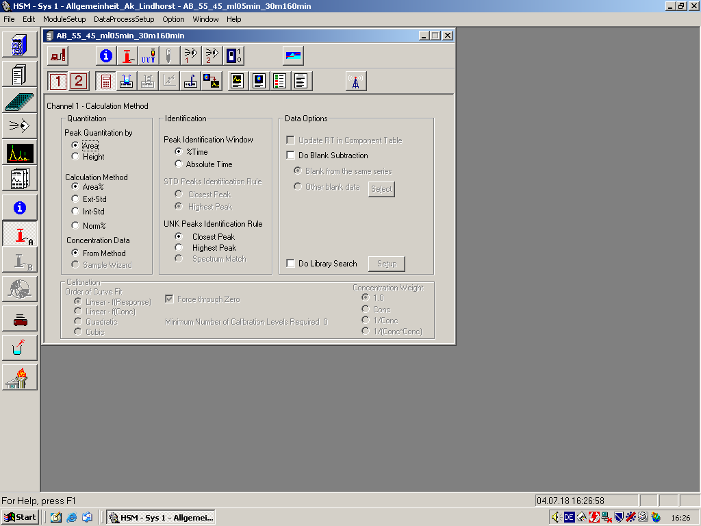
Calculation Method
Use this command to review or modify the calculation method.
Tool Bar Shortcut
| Dialog Box Options | |
|---|---|
| Quantitation | Peak Quantitation by: A peak can be measured according to its Area or its Height. If you select Height, the peak height is measured as the distance from baseline to peak maximum.
Calculation Method: Select one of the four available methods: Area%/Height% Method, External Standard Method (Ext Std), Internal Standard (Int Std), and Normalized % Method (Norm%). Concentration Data: Select From Method when you wish the program to use concentration data from the Method when performing report processing and calibration. If the Sample Wizard program is available, select Sample Wizard when you wish the program to use concentration data from the Sample Wizard. When you select Sample Wizard, theDatei:Concentration table.png button on the tool bar and the Concentration Table command on the DataProcessing menu are disabled. Note: It is not necessary that both channel 1 and 2 have concentration data come from the same source. When Height%/Area% is selected, the HSM automatically selects From Method and disables Sample Wizard. |
| Identification | Peak Identification Window: Determines the tolerance that the actual retention time of a peak can deviate from the expected retention time of that component. If you select %Time, a percentage of the absolute retention time is used for the identification window. If you select Absolute Time, the identification window is defined in minutes. This absolute time length for tolerance is constant regardless of the retention time. See Identification Window.
STD Peaks Identification Rule: Specifies how STD peaks are identified. This section is disabled if Area%/Height% is selected. Select Closest Peak or Highest Peak. Closest Peak is the peak having a retention time closest to that of the component specified within the specified window.Highest Peak is the highest peak in the specified window.UNK Peaks Identification Rule Specifies how UNK peaks are identified. Select Closest Peak, Highest Peak, or Spectrum Match. Spectrum Match is available only when a DAD detector is configured for the channel and when the Calculation Method is not Area%/Height%.Closest Peak: The peak having a retention time closest to that of the component specified within the specified window.Highest Peak: The highest peak in the specified window.Spectrum Match: This option enabled only when the selected Channel 1 Detector is either L-4500, L-7450, or L-7455 DAD Detector. The UNK peak is identified by comparing the spectrum of each peak in the specified window with the spectrum of the STD component. The best match is identified as the component in UNK.Also see Peak Identification for more information. |
| Data Options | Update RT in component table: if the box is checked, the HSM will replace the RT for each component with an average RT determined from all STD injections selected for data processing. This will allow the program to cope with retention time drift gradually. This option is not available is Area(Height)% is selected as the Calculation Method.Do Blank Subtraction: Check the box for blank subtraction.Blank from the same series: Check to use the blank injection data from the same data series in subtraction. If there are more than one blank injection data in the series, the rules for subtracting Blank data from the Same Series are followed.Other blank data: Check to select blank data from other series within the same application. To select other blank data, click on the Select pushbutton to display the Blank Data dialog, where you can select a blank data from the desired series. The rules for subtracting Blank Data from Other Series are followed by the HSM.Do Library Search: Select the check box to enable a Library Search. Click on Setup button to set up Library Search options. See Setup Library Search dialog. |
| CalibrationThis section is disabled if Area% is selected in Quantification. | Order of Curve Fit: Specifies the order of a polynomial function that is fitted to the standard data points. Select either Linear, Quadratic, or Cubic. Force through Zero: Specifies whether calibration curves are forced through the origin. If you check the box, the calibration curve is forced through the origin. If you do not check the box, the calibration data points dictate where the calibration curve intersects with the Y axis. The diagram below illustrates calibration curves with the Force through Zero option both on and off.
Concentration Weight: Select a desired weighing factor for weighted least square analysis. Default is 1.0 which is unweighted least square analysis.Also See: Calibration Curve (Quantification).Minimum Number of Calibration Levels Required is a read-only field. It is determined based on the Order of Curve Fit and the selection of Force through Zero: Fitting Condition Standards Required Linear 2 Linear + Force Zero 1 Quadratic 3 Quadratic + Force Zero 2 Cubic 4 Cubic + Force Zero 3 |
